

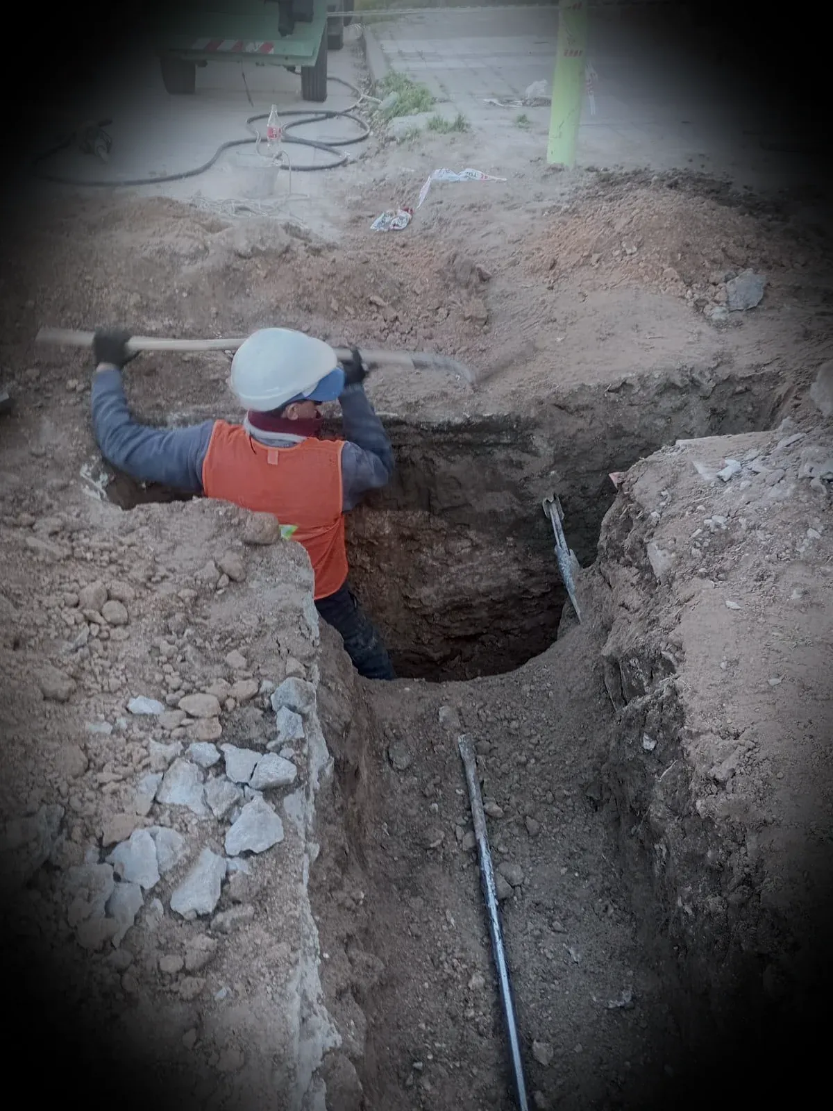
Fibre optics · backbone
Aerial and underground fibre-optic backbones
We assess fibre-optic backbones by reviewing routes, ducts, supports, chambers, cable, splices, ODFs and testing. The offer defines tasks and documentation for the specific project.
Scope, resources, qualifications and schedule are confirmed following technical review of the project.
Scope inputs
A backbone is designed for continuity, maintainability and restoration.
A route may combine poles, power lines, ducts, chambers, buildings and crossings. The design must preserve bend radii, reserves, access, identification, mechanical protection and a splice strategy that supports operation and repair.
Route and support works
Survey, ducts, chambers, trays, poles, supports and crossings within the defined package.
- Aerial, underground or mixed
- Clearance and occupancy
- Maintenance access
Cable and terminations
Cable installation, reserves, closures, branches, ODFs, patching and labelling.
- Controlled radii and tension
- Sealing and protection
- End-to-end naming
Testing and handover
OTDR, power, continuity, matrix, drawings, photographs and dossier.
- Optical budget
- Event table
- Redlines and source files
Method
Executable backbone stages
Architecture
Origins, destinations, capacity, redundancy, nodes, growth and service criteria.
Survey
Route, occupancy, crossings, chambers, structures, access, permits and risks.
Engineering
Cable, ducts, hardware, reserves, closures, ODFs, splices and optical budget.
Construction
Ducts, supports, stringing, reserves, closures and terminations.
Testing
Continuity, OTDR, power, identification and event correction.
Close-out
Drawings, matrix, protocols, photographs, inventory and dossier.
Scope inputs
Definitions that prevent an ambiguous network
These inputs turn assumptions into controlled decisions.
- Origins, destinations and transported services
- Current fibre count and forecast growth
- Available ducts, chambers and supports
- Route, distances, crossings and permits
- Cable type and mechanical protection
- Splice, branch, reserve and access points
- ODFs, connectors, patch cords and terminal equipment
- Redundancy, rings and contingency strategy
- Optical budget and acceptance criteria
- Drawing, inventory and dossier format
Commercial engineering
Decisions that change total cost
New or existing route
Actual duct, chamber and support condition drives cleaning, repairs, civil works and time.
Number of nodes
Each branch adds closures, reserves, fusion, identification, testing and maintenance.
Redundancy
A ring or alternative route raises investment but reduces outage risk.
Documentary close-out
A network without inventory and as-built records is cheaper initially and far more expensive when it fails.
Next step
Deliverables to agree for acceptance
The scope must define which records, measurements and documents apply to the contracted package.
- Route drawing and design basis
- Cable, duct, hardware, closure and ODF BOM
- Drum, reserve and splice plan
- Fibre matrix and naming standard
- OTDR/power results and event table
- As-built, inventory and final dossier
Related technical resources
Continue the technical path.
FAQ
Questions that change scope, price or acceptance.
Can you deliver a hybrid route?
Yes. The scope can integrate aerial sections, ducts, trays, chambers, buildings and crossings under one continuity matrix and document set.
Are civil works included?
They can be included or coordinated with a civil contractor. Excavation, reinstatement, chambers, ducts, permits and testing must be defined.
How is cable reserve determined?
By nodes, structures, chambers, ODFs, splices, repairability, bend radii and client standards—not by an unlocated percentage.
Do you provide a network inventory?
The close-out can include cable, drum, closure, tray, fibre, port, location, status, tests and as-built drawing.
Next step
Turn the route into a measurable, maintainable network.
Share origin, destination, route, capacity, available infrastructure and target date. We return a scope map and missing inputs.