

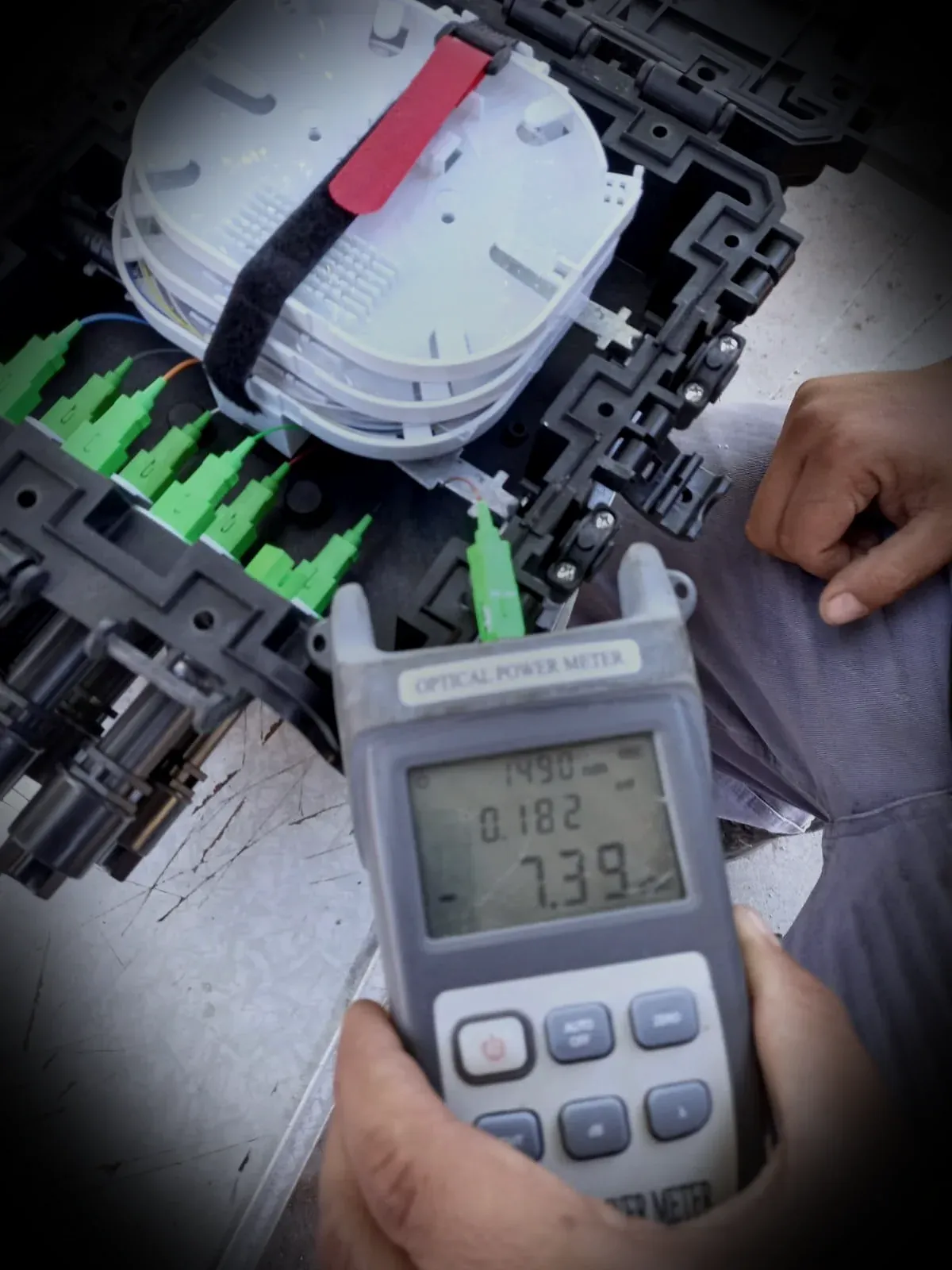
Fibre optics · acceptance
Fusion splicing and bidirectional OTDR testing
We assess identification, preparation, fusion, tray management, testing and per-fibre documentation. Acceptance criteria and required equipment are confirmed before quotation.
Scope, resources, qualifications and schedule are confirmed following technical review of the project.
Scope inputs
An acceptable splice is not enough when the network is not traceable.
The result must show which fibre was spliced, in which tray, with what continuity, where events are located and the loss of the section. Matrix, labelling and acceptance criteria are released before opening the cable to prevent rework and unauditable results.
Preparation and fusion
Entry, identification, stripping, cleaning, cleaving, arc fusion, protection and tray organisation.
- OPGW, ADSS and dielectric cable
- Closures, ODFs and boxes
- Visual control and protection
Testing and diagnostics
Bidirectional OTDR, power meter where required, event table and loss analysis.
- 1310 / 1550 nm
- Launch and receive fibres
- Reflective and non-reflective events
Documentation
Fibre matrix, naming, native traces, reports, photographs and as-built drawings.
- File per section and fibre
- Controlled matrix revisions
- Acceptance-ready dossier
Method
Optical acceptance workflow
Approved matrix
Continuity, use, reserve, colours, trays, ends and naming are defined.
Node preparation
Closure, sealing, cable entries, reserves and work conditions are verified.
Controlled fusion
Each fibre is cleaned, cleaved, fused, protected and routed to the matrix.
Initial check
Abnormal events are detected before the node is permanently closed.
Final testing
Traces are acquired from both ends at agreed wavelengths.
Dossier
Results, exceptions, photographs, redlines and source files are consolidated.
Scope inputs
Information required before intervention
These inputs turn assumptions into controlled decisions.
- Type, brand, construction and fibre count of each cable
- Node, closure, ODF and end-point drawings
- Fibre allocation matrix or criteria to build it
- Colour code, trays and naming convention
- Estimated length and optical budget
- Splice and end-to-end acceptance criteria
- Wavelengths, pulse width and index settings
- File format, naming and traceability requirements
- Intervention window and network status
- Patch cords, launch and receive fibres
Commercial engineering
Common causes of rejection
Unreleased matrix
Splicing first and deciding later creates crossed fibres, no-destination fibres and inconsistent documents.
One-way testing
It can hide backscatter differences and distort event evaluation.
Changing naming
Closure, tray, fibre, file and drawing must use the same code.
Closing before diagnosis
High-loss events must be located and corrected before sealing and release.
Next step
Deliverables to agree for acceptance
The scope must define which records, measurements and documents apply to the contracted package.
- Splice and fibre allocation matrix
- Closure, tray and end-point register
- Native OTDR traces per direction and fibre
- Consolidated event and loss table
- Exception and corrective-action report
- Final dossier with redlines and photographs
FAQ
Questions that change scope, price or acceptance.
What does bidirectional OTDR mean?
The same section is measured from both ends. Events are compared or averaged to the agreed acceptance method, reducing errors caused by fibre and instrument backscatter differences.
Do you hand over the native test files?
The dossier can include source traces, exported reports, event tables, naming and fibre matrices in the contractual format.
Can you intervene on an existing network?
Yes, with an agreed window, identification and contingency plan. Continuity, affected services, reserves and restoration sequence are validated before cutting.
What drives splicing duration?
Fibre count and construction, cable condition, access, closures, trays, matrix, labelling, testing, rework and dossier format.
Next step
Set the acceptance criteria before the first cut.
Send fibre count, nodes, available matrix, estimated length and required deliverable format. We return scope, missing inputs and work sequence.